Appendix A: Restoring Factory Default Settings
In the event that the IP address or passwords are forgotten, the module may be restored to its original factory default settings.
1. Remove the DC power from the unit.
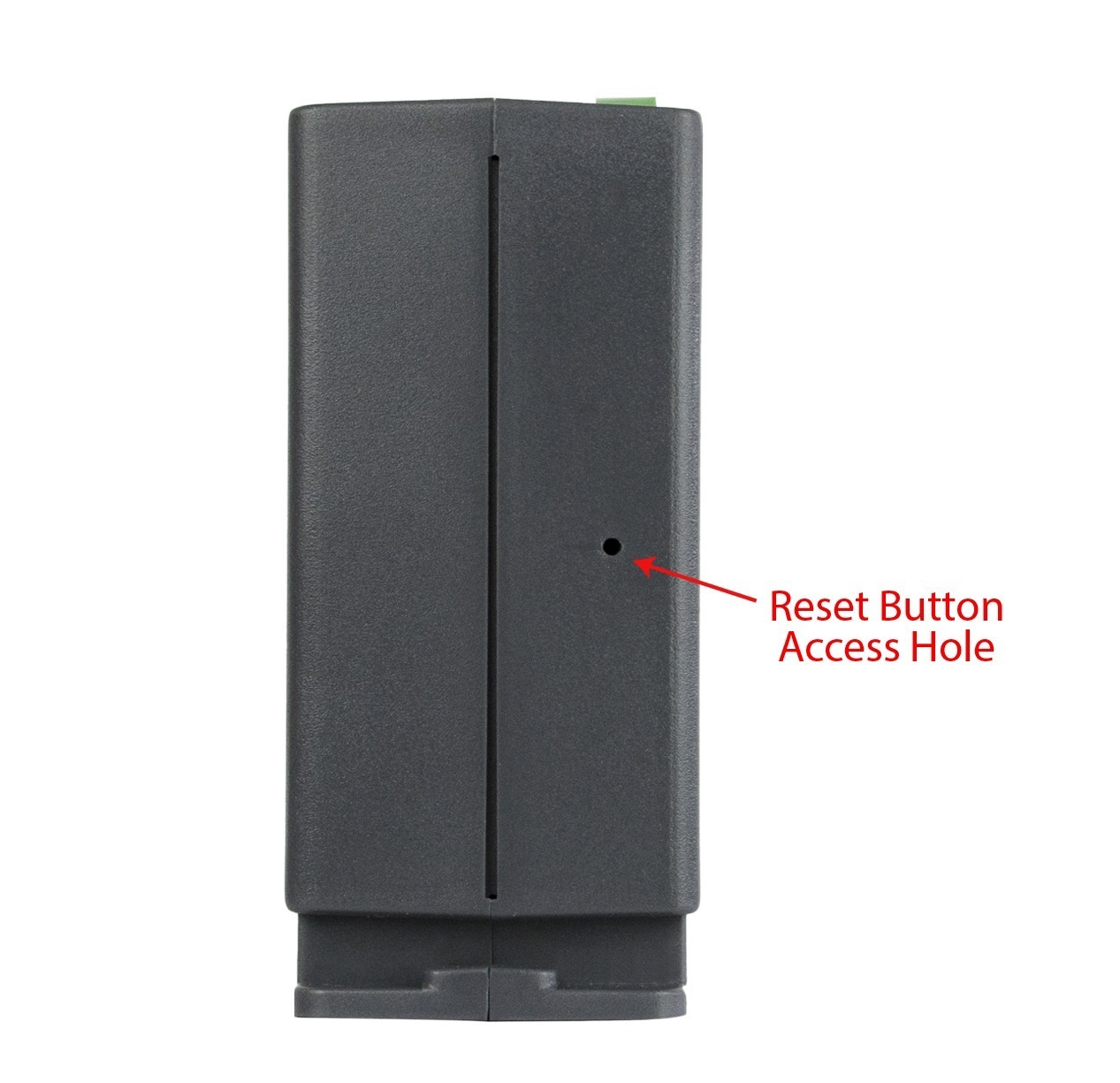
2. Use a thin, non-conductive object (such as a toothpick) to press and hold the small button located on the bottom of the unit. When the object is inserted, a tactile feedback can be felt as the button is depressed.
CAUTION: Do not use metal objects for this function
3. While depressing the button, apply power. While holding the button, you should see both the Link and Activity lights on the Ethernet port flash.
4. Continue holding the button for five seconds before releasing the button. All settings will be back to the original factory defaults. log.txt and syslog.txt are retained.
5. Refer to Establishing Communications for Setup to begin reconfiguration of the module.
Appendix B: Installing New Firmware
From time to time, updates are made to the module’s firmware. As an industrial device and unlike many consumer products, firmware updates are recommended only on an as-needed basis. The firmware can be updated in the field, or remotely. Remote field updates updates are only available on devices with firmware version 3.12 or higher. The procedure for updating the firmware is outlined below. Please note that it is important that this procedure is followed precisely.
If your device has firmware version 3.12, it can receive remote field updates updates with each new release. Updating firmware remotely in version 3.12 also brings a big and welcome change; When updating remotely, the logic and settings of your device will be saved and remain after reset.
Updating the device remotely is simple:
1. Click “Upload Firmware” and select the desired firmware file from the file explorer on your computer.
2. The device will then run a quick test to ensure that all settings and logic still function on the new firmware version.
If the device finds an incompatibility, it will revert to the previous firmware and maintain all settings and logic.
For devices below firmware version 3.0, follow the steps below:
Requirements
The firmware update software requires Windows 7/8/10.
Setup
1. Updating firmware will not automatically save settings, scripts, etc. Before proceeding with the firmware update, please back up all settings files and Basic scripts.
2. Contact technical support if a firmware update is needed and a download link will be provided. Only a module’s image can be installed on the module, so make sure the correct image is being downloaded.
3. bootloader.exe will connect to the module using default IP address 192.168.1.2, not the address currently assigned to the module. After the update, all settings will be lost and the device will return to its default IP address of 192.168.1.2. Configure the PC to the same subnet as the IP address 192.168.1.2, such as 192.168.1.10. For instructions on doing this see Section Establishing Communications for Setup.
Note: The IP address of the module will automatically be set to the default 192.168.1.2 during the update process. Since the module supports Auto Negotiation, a crossover cable is not necessary.
4. Open the bootloader.exe utility on the computer by double clicking on the downloaded file.
5. Within the ControlByWeb™ Programmer utility programmer, select File, then Open. Specify the firmware image downloaded from the ControlByWeb™ website.
Device Upgrade Procedure
Carefully follow the following steps to put the module into bootloader mode and perform the upgrade:
1. Remove DC power from the module.
2. Using a small, non-conductive tool, press and hold the reset button.
3. While holding the reset button, apply power to the module. The LINK and ACT lights will flash. Continue to hold the reset button for the next step.
4. While holding the reset button, press the Upload Firmware button at the bottom of the ControlByWeb™ Programmer window. After the programming process begins, the reset button can be released.
5. Programming will take approximately 60 seconds, the LINK LED will stop flashing and remain lit. The module will be set to factory defaults with an IP address of 192.168.1.2.
6. Refer to Section Establishing Communications for Setup to reconfigure the device. Verify the new version of firmware has been installed by viewing the default setup page with a web browser (http://192.168.1.2/setup.html).
Appendix C: Accessing the Device Over the Internet
The module can be monitored and/or controlled from a remote location over the Internet. Once the module can be accessed on the local network, almost all of the settings required to provide remote access are in the router and not in the module.
This guide is not meant to be a tutorial in router setup, but rather to provide a basic overview of remote access. For specific details, the user should refer to the instruction manual for the router on the local network. Users not familiar with basic IP networking should study one or more basic IP networking tutorials before proceeding (many tutorials are available on the Internet).
IP Addresses
Every device on the Internet is identified by a unique address called an IP (Internet Protocol) address. IP addresses are somewhat similar to mailing addresses in that they identify the precise logical location of the device on the Internet. The IP address identifies the global region down to the network and then the specific device on that network. IP addresses are globally maintained and assigned by an entity called the Internet Assigned Numbers Authority (IANA). IP addresses consist of four sets of numbers that range from 0 to 255 and are separated by a decimal. For example, 192.168.200.167 is an IP address.
Every device that is “directly” connected to the Internet uses a “public” IP address. The module can be assigned a public IP address for direct connection to the Internet. Typically, a public IP address to would only be assigned to the module when it is the only device on the local network. The IP address would be obtained from an Internet Service Provider (ISP).
Due to the limited number of public IP addresses, private networks can be set up with “private” IP addresses. These addresses are used within a local network and have no global designation, they are not routed on the Internet. The following address blocks are designated for private networks (where x represents decimal numbers from 0 to 255): 192.168.x.x, 10.x.x.x, and 172.16.x.x.
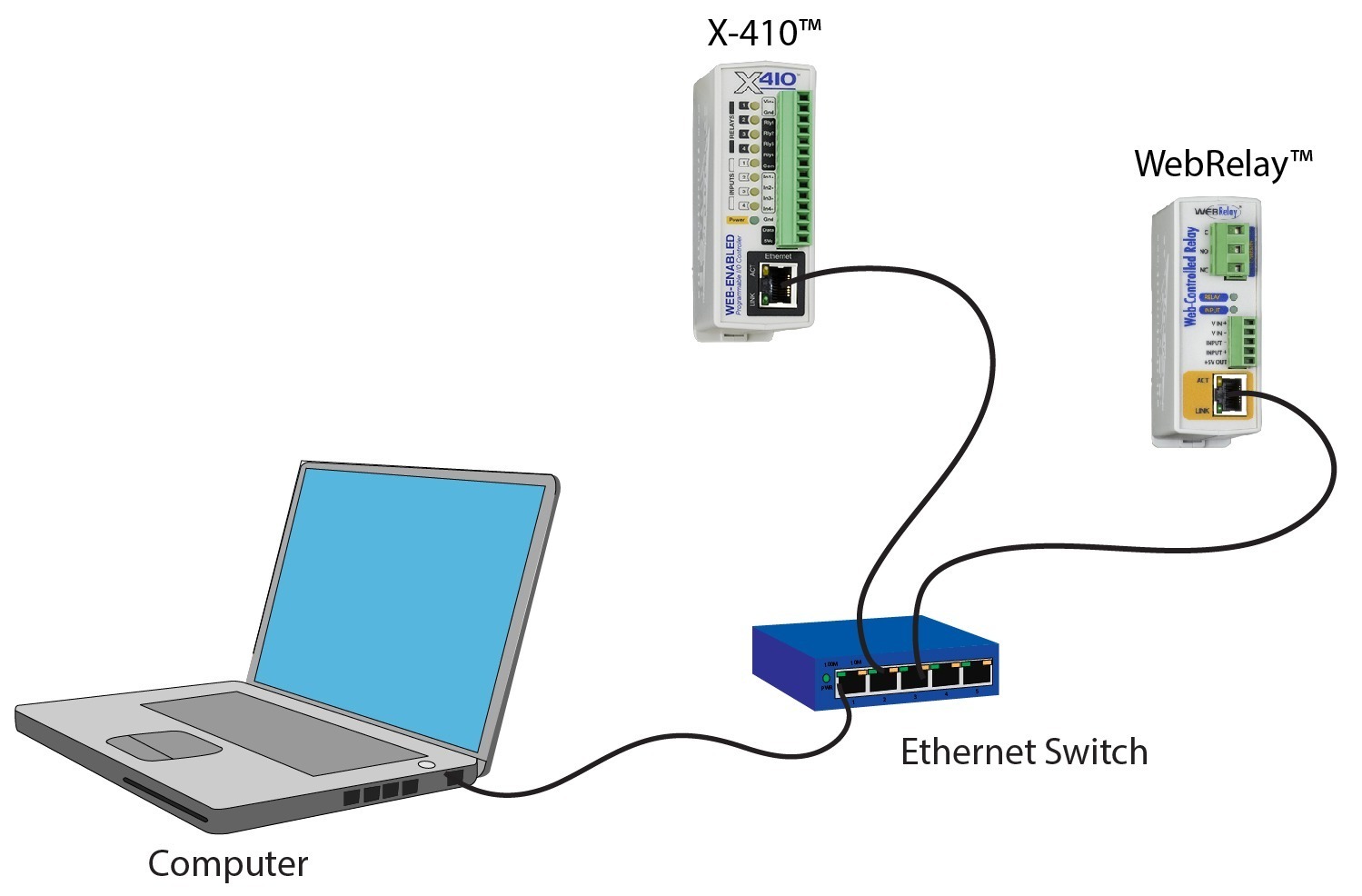
A Simple Local Area Network
A small Local Area Network (LAN), can be made up of two or more computers or other devices connected to an Ethernet switch. Each device on the network is assigned a unique private IP address. For example, consider a simple network that consists of a computer, an X-410, and a WebRelay™. In this example, the computer is assigned an IP address of 192.168.1.10, the X-410 has the IP address of 192.168.1.25 and a WebRelay™ has and IP address of 192.168.1.26. A person using the computer can access the X-410 by entering its IP address in the URL line in the browser, http://192.168.1.25. Similarly, the WebRelay™ can be accessed by entering its unique private IP address in the URL line in the browser, http://192.168.1.26.
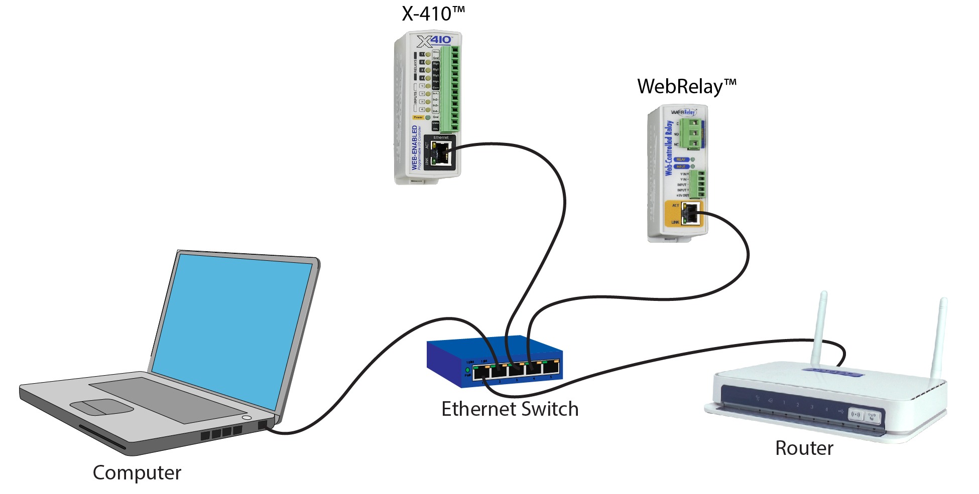
A Simple LAN connected to the Internet
The LAN in the example above can be connected to the Internet by adding a router and an Internet connection. The router has two network connections. It has an Ethernet network connection to the LAN and another connection to the Internet. Often the Internet connection is called a Wide Area Network (WAN) connection. Each network connection on the router has an IP address. In our example, the IP address on the LAN side of the router has an address of 192.168.1.1. The IP address on the WAN side of the router has an IP address that has been assigned by the Internet Service Provider, such as 203.0.113.254.
In the example, when a user on the computer needs to access a server on the Internet, the computer sends the request to the router at 192.168.1.1. The router sends the request to the ISP server on the Internet. The ISP server does not send the response directly to the computer on the LAN, but to the router at the IP address of 203.0.113.254. The router then forwards the response to the computer. This way, all devices on the LAN share a single public IP address. This is called Network Address Translation (NAT).
Port Forwarding
The router can be configured to allow outside access to the ControlByWeb devices. All requests from the Internet to any device on the local network must use the public IP address (203.0.113.254). With only a single IP address, TCP ports are used to identify the intended device for the incoming message.
Using the mailing address analogy, the port is similar to a post office box. The IP address specifies the location, and the port specifies the specific recipient. Port numbers can be set to any number between 1 and 65535. However, many port numbers are reserved for specific applications and should be avoided. As a general rule, numbers above 8000 are safe to use. All of the ControlByWeb™ devices come from the factory with the HTTP port set to 80, which is the standard port for HTTP. In the example above, the X-410 HTTP port will be changed to port 8000 and WebRelay™ port will be changed to 8001. Once the ports are changed in the two ControlByWeb™ devices, the router must be set up for port forwarding.
Port forwarding associates the IP address of each local device with an assigned port. In the above example, the address 192.168.1.25 for the X-410 would be associated with port 8000. The address 192.168.1.26 for WebRelay™ would be associated with port 8001. The X-410 would be accessed from the Internet by entering the public IP address of the router, plus the port number assigned to the X-410 in the URL window of the browser, http://203.0.113.254:8000. All Internet requests to the router for port 8000 would be forwarded to the X-410. Similarly, all request for port 8001 would be forwarded to WebRelay.
Note: When an HTTP request comes in to the router without the specific port specified (http://203.0.113.254), the router will handle this as a port 80 request (default HTTP port). In other words, http:// 203.0.113.254 is exactly the same as http://203.0.113.254:80.
Router configuration can vary widely. Some routers have the capability of translating the addresses and the ports, which would require no port configuration change on the ControlByWeb device. For example, the router would be configured so that messages sent to http://203.0.113.254:8000 would be forwarded to http://203.0.113.254:80, which is the default HTTP port.
An example screenshot of a router configuration is given below. This setup allows the two ControlByWeb™ devices in the above example to be accessed remotely from the Internet.
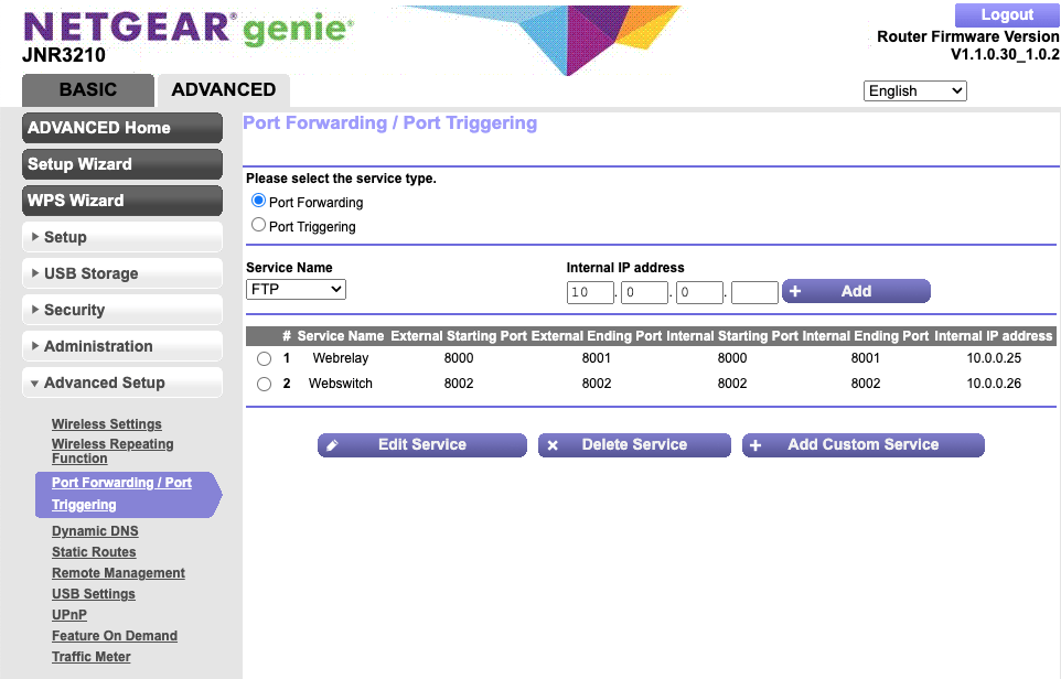
Example of Port Range Forwarding
Note: This screenshot is simply an example of a typical router setup page. Routers will vary.
Accessing Setup Pages
After changing ports, the setup pages are accessed on a local network as described below:
http://(ControlByWeb Device’s Local IP Address):(Port Number)/setup.html
For example, to access the setup pages when the port is set to 8000, the following command would be used:
http://192.168.1.25:8000/setup.html
To access the ControlByWeb™ devices from the Internet, enter the public IP address of the router plus the port number of the desired device in the following format:
http://(Public IP Address of Router):(Port Number of Device)/setup.html
Using the example above, the following line would be used to access the setup page of the X-410:
http://203.0.113.254:8000/setup.html
Appendix D: Specifications
Power Requirements:
| Model | Input Voltage |
| X-400-I | 9-28VDC |
| X-400C-I | 9-28VDC |
| X-401-I | 9-28VDC |
| X-401-E | Power Over Ethernet (*) and/or 9-28VDC. |
| X-404-I | 9-28VDC |
| X-404C-I | 9-28VDC |
| X-405-I | 9-28VDC |
| X-405-E | Power Over Ethernet (*) and/or 9-28VDC. |
| X-406-I | 9-28VDC |
| X-406-E | Power Over Ethernet (*) and/or 9-28VDC. |
| X-408-I | 9-28VDC |
| X-408-E | Power Over Ethernet (*) and/or 9-28VDC. |
| X-410-I | 9-28VDC |
| X-410-E | Power Over Ethernet (*) and/or 9-28VDC. |
| X-412-I | 9-28VDC |
| X-412-E | Power Over Ethernet (*) and/or 9-28VDC. |
| X-417:1-I X-417:2-I X-417:3-I X-417:4-I X-417:5-I | 9-28VDC |
| X-418-I | 9-28VDC |
| X-418-E | Power Over Ethernet (*) and/or 9-28VDC. |
| X-420-I | 9-28VDC |
| X-420-E | Power Over Ethernet (*) and/or 9-28VDC. |
*48V injected into Ethernet Line as per 802.3af specification, POE Class 1 (0.44Watt to 3.84Watt range)
X-400-I Input Current: Values at 25C
| Power Supply | Typical Current (no expansion modules) | Max Current (X-400 + 1.7A for expansion modules) |
| 9 VDC | 134 mA | 1.834 A |
| 12 VDC | 101 mA | 1.801 A |
| 24 VDC | 55 mA | 1.755 A |
X-400C-I Input Current: Values at 25C
| Power Supply | Typical Current (no expansion modules) | Max Current (no expansion modules) | Max Current (X-400 + 1.7A for expansion modules) |
| 9 VDC | 190 mA | 240 mA | 1.94 A |
| 12 VDC | 130 mA | 185 mA | 1.85 A |
| 24 VDC | 80 mA | 95 mA | 1.80 A |
X-401 Input Current: Values at 25C
| Power Supply | Typical No Relays or Inputs On | Typical 2 Relays and Inputs On |
| 9 VDC | 107 mA | 233 mA |
| 12 VDC | 83 mA | 180 mA |
| 24 VDC | 46 mA | 108 mA |
X-404-I Input Current: Values at 25C
| Power Supply | Typical Current (no modbus sensors) | Max Current (X-404 + 1.7A for modbus sensors) |
| 9 VDC | 134 mA | 1.834 A |
| 12 VDC | 101 mA | 1.801 A |
| 24 VDC | 55 mA | 1.755 A |
X-404C-I Input Current: Values at 25C
| Power Supply | Typical Current (no expansion modules) | Max Current (no expansion modules) | Max Current (X-404C + 1.7A for modbus sensors) |
| 9 VDC | 190 mA | 240 mA | 1.94 A |
| 12 VDC | 130 mA | 185 mA | 1.85 A |
| 24 VDC | 80 mA | 95 mA | 1.80 A |
X-405 Input Current: Values at 25C
| Power Supply | Typical Current (1 sensor) |
| 9 VDC | 113 mA |
| 12 VDC | 90 mA |
| 24 VDC | 50 mA |
X-406 Input Current: Values at 25C
| Power Supply | Typical Current (no sensors) | Typical Current (4 sensors) |
| 9 VDC | 110 mA | 115 mA |
| 12 VDC | 89 mA | 90 mA |
| 24 VDC | 50 mA | 50 mA |
X-408 Input Current: Values at 25C
| Power Supply | Typical Current (8 inputs off) | Typical Current (8 inputs on) |
| 9 VDC | 115 mA | 175 mA |
| 12 VDC | 87 mA | 133 mA |
| 24 VDC | 49 mA | 74 mA |
X-410 Input Current: Values at 25C
| Power Supply | Typical No Relays or Inputs On | Typical 4 Relays and Inputs On |
| 9 VDC | 110 mA | 240 mA |
| 12 VDC | 85 mA | 180 mA |
| 24 VDC | 50 mA | 100 mA |
X-412 Input Current: Values at 25C
| Power Supply | Typical No Relays On Analog Inputs Single Ended | Typical All Relays On Analog Inputs Single Ended | Typical No Relays On Analog Inputs 4-20mA | Typical All Relays On Analog Inputs 4-20mA |
| 9 VDC | 118 mA | 230 mA | 135 mA | 245 mA |
| 12 VDC | 90 mA | 172 mA | 103 mA | 184 mA |
| 24 VDC | 47 mA | 90 mA | 54 mA | 96 mA |
X-417 Input Current: Values at 25C
| Power Supply | Typical 5 Outputs in 0-5V | Typical 5 Outputs in 4-20mA @ 20mA, 200ohm | Typical 5 Outputs in 4-20mA @ 20mA, 1kohm |
| 9 VDC | 222 mA | 294 mA | 529 mA |
| 12 VDC | 166 mA | 226 mA | 380 mA |
| 24 VDC | 93 mA | 115 mA | 196 mA |
X-418 Input Current: Values at 25C
| Power Supply | Typical Current | Typical Current (4x 4-20mA mode) |
| 9 VDC | 134 mA | 152 mA |
| 12 VDC | 103 mA | 115 mA |
| 24 VDC | 58 mA | 65 mA |
X-420 Input Current: Values at 25C
| Power Supply | Typical Current |
| 9 VDC | 175 mA |
| 12 VDC | 135 mA |
| 24 VDC | 75 mA |
I/O Connectors
5-position, removable terminal strip, 3.81 mm spacing
(replacement part number, Phoenix Contact 1827004)
14-position, removable terminal strip, 3.81 mm spacing
(replacement part number, Phoenix Contact 1803691)
Expansion Connector (X-400) Provides power and communication for expansion modules.
| Connector: | Ribbon cable,10-conductor, polarized, 2×5-position, 0.100” pitch |
| Communications: | RS-485 |
RS-485 Connector (X-404) Provided power and communication with modbus sensors.
| Connector: | 5-position, removable terminal strip, 3.81 mm spacing |
| Communications: | RS-485 |
Cellular Antenna Connector (Cellular Devices only): Female, type SMA
1-Wire Sensor Input
| +5Vout Output: | 5.0V, 100mA max |
Relay Contacts (X-401)
| Number of relays: | 2 |
| Contact Form: | SPDT (form C) |
| Contact Material: | AgSnO2 |
| Contact Resistance: | < 50 milliohms initial |
| Internal Relay Mechanical Endurance: | 10,000,000 operations min. (under no load) |
| Internal Relay Electrical Endurance: | 100,000 operations average (under rated load) |
| Max Voltage: | 28VAC, 24VDC |
| Max Current: | 3A |
| Control Options: | On/Off or Pulsed |
| Pulse Timer Duration: | 100ms to 86400 Seconds (1-day) |
Relay Contacts (X-410)
| Number of relays: | 4 |
| Contact Form: | SPST (form A) |
| Contact Material: | AgNi |
| Contact Resistance: | milli-ohm max |
| Internal Relay Mechanical Endurance: | 5,000,000 operations min. (under no load) |
| Internal Relay Electrical Endurance: | 100,000 operations average (under rated load) |
| Max Voltage: | 28VAC, 24VDC |
| Max Current: | 1A |
| Control Options: | On/Off or Pulsed |
| Pulse Timer Duration: | 100ms to 86400 Seconds (1-day) |
Digital Inputs (X-401, X-408, X-410)
| Number of Inputs: | X-401: 2; X-408: 8; X-410: 4 |
| Minimum Hold Time (high or low): | 2.5mS |
| Input Current (Iin): | 950uA @ 4V, 8.5mA @ 26V |
| Reverse Voltage (Vr): | 6V max |
| Vin: | 26V (max) |
| Vin Hi: | 4V (min) |
| Vin Lo: | 1.5V (max) |
| Input Counter (24 bit): | 16,777,215 (max count) |
| Max Counter Frequency Input: | 200Hz |
Analog Outputs (X-417)
| Number of Outputs: | 1-5 (individually configurable) |
| Output Ranges: | 0-5V, 0-10V, ±5V, ±10V, 4-20mA (software selectable) |
| Resolution: | 16-bit DAC (0-65535) |
| Linearity Error: | -count, monotonic DAC |
| Current Output (Voltage mode): | 10mA max (min load = 1K), 30mA max short circuit |
| Voltage Output Inaccuracy: | .2% FSR, includes offset error, gain error and nonlinearity |
| Max Load Capacitance: | 20nF (no load), 5nF (1K load) |
| Current Output Range: | 4-20mA |
| Max Voltage in Current Mode | 24V |
| Current Output Inaccuracy: | .2% FSR, includes offset error, gain error and nonlinearity |
| Isolated Power Supply: | Internal DC-DC converter |
| Isolation: | Galvanic, 1500 VAC |
| ESD Protection: | Integrated 15kV protection (IEC61000-4-2) |
| Output Protection: | Integrated over-temperature, open-line and short circuit protection |
| Output Alarms: | Open current loop, high internal temperature |
| Load Type: | Grounded, COM of all 5-channels are connected together |
| Output at power up: | Programmable |
Analog Inputs (X-412, X-418, X-420)
| Number of channels: | 8ea (X-418), 4ea (X-420) |
| Resolution: | 16-bit, SAR |
| Type: | Channels 1-4: Single ended, differential or 4-20mA (0-20mA) Channels 5-8: Single ended or differential Channels 1-8: Pseudo digital input |
| Input Range (programmable): | 1.28V, ±.56V, ±.12V, ±0.24V, ±0.48V (differential) |
| Max Input Voltage Range (Vin): | -12.5V < Vin < +12.5V |
| Input Impedance (Zin): | >500Meg Ohm |
| Channel Off Leakage: | 0.6nA (typ) |
| Input Common Mode Rejection: | >100dB |
| Total Unadjusted Error: | -9LSB (min), +9LSB (max) |
| Voltage Reference Drift: | 5 ppm/ |
| Internal 0-20mA input shunt: | 200.0-ohm, .1%, 25ppm (uses .12V range) |
| Logging Rate: | 25 Hz |
| Sample Rate: | 50 Hz |
Pseudo Digital Inputs (X-412, X-418, X-420)
| Vih (high-level input voltage): | 3.5V |
| Vil (low-level input voltage): | 1.5V |
| Sample Rate: | 50 Hz |
Digital Input/Output (X-420)
| Number of Digital I/O: | 2ea, programmable as an input or output |
| Pull-up/Pull-down Resistor: | 47K |
| Vih (high-level input voltage): | 3.5V min |
| Vil (low-level input voltage): | 1.5V max |
| Vout: | 5V CMOS logic thru a 49.9-ohm resistor |
| Debounce: | Configurable, 0 to 250mS |
| Pulse Counters: | 2ea, 24-bit |
| Max Counter Frequency Input: | 200Hz |
Frequency Input (X-420)
| Type: | AC coupled, referenced to Gnd, sine or square wave (works with millivolt magnetic wind speed sensors) |
| Input Voltage: | +/- 12 VDC, 30Vpp AC max |
| Hysteresis: | 25mV |
| Frequency: | 0-20KHZ |
| Vin @ 1 Hz | 50mVpp min |
| Vin @ 10 Hz | 50mVpp min |
| Vin @ 100 Hz | 60mVpp min |
| Vin @ 1 kHz | 80mVpp min |
| Vin @ 10 kHz | 700mVpp min |
| Vin @ 20 kHz | 1.7Vpp min |
Network
| 10 Base-T or 100 Base-T Ethernet IPv4 (10 Mbit/s or 100 Mbit/s) |
| Static IP address assignment or DHCP |
| HTTP port selectable |
| HTTPS port selectable |
| Standard 8-pin RJ-45 modular socket, with auto-negotiation |
| Supported Protocols: HTTP, HTTPS, SSL, XML, Modbus TCP/IP, SNMP V1,2C,V3, SMTP |
LED Indicators
| Power | Green |
| Network Linked | Green |
| Network Activity | Yellow |
| Relay | Yellow |
| Digital Input | Yellow |
Email Alerts
| Email Addresses: | Configurable, up to 8 addresses |
| Encrypted Email Alerts: | STARTTLS and TLSL/SSL |
| Status Alerts: | Analog and digital inputs, etc. |
| Other Alerts: | Alert logic is fully customizable |
Real-Time Clock
| Manual or NTP (Network Time Protocol) setup |
| NTP Sync configurable for once, daily, weekly, or on power-up |
| Automatic daylight savings adjustment |
| Battery (capacitor) backup: Real-time clock, 1 register, 2 counters, 64 relay states (local and expansion modules only) |
| Backup Duration: 24 hours |
Nonvolatile Memory
| Flash Memory |
| All user settings are stored in nonvolatile memory. Settings will not be lost when power is disconnected. |
Logging
Stored in Nonvolatile Flash
Circular Buffer
512-Kbyte (up to 8192 log entries depending on configuration)
Unlimited data storage possible through sending the log through email or FTP services.
Password Settings
Password protection for Administrators (setup pages)
Optional password protection for Managers
Optional password protection for Users (control page)
Base 64 Password Encoding
Password Length: 18 character, case sensitive
Scripts
Implement special or custom features with a BASIC script
Max size : 4-Kbytes
Environmental
Operating Temperature: -40° to 65.5° (-40° to 150°)
Storage Temperature: -40° to 85° (-40° to 185°)
Altitude: up to 2000m
Humidity: 5-95% non-condensing
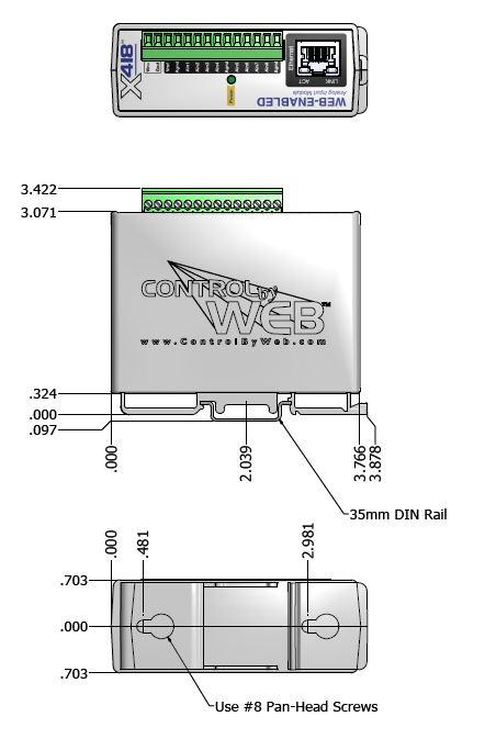
Mechanical
Size: 1.41 x 3.88 x 3.1 in. (35.7 x 98.5 x 78 mm), not including connector
Weight: 5 oz (142 g)
Electromagnetic Compliance
IEC CISPR 22, CISPR 24
EU EN55024, EN55022
X-400-I: FCC 47CFR15 (Class B)
Cellular Modules:
Contains FCC ID: N7NHL7648
Contains IC: 2417C-HL7648

Appendix E: Trademark and Copyright Information
This document is Copyright 2005-2023 by ControlByWeb, LLC. All rights reserved.
X-400™, X-401™, X-404™, X-405™, X-406™, X-408™, X-410™, X-412™, X-417™, X-418™, X-420™, WebRelay™, ControlByWeb™, and Xytronix Research & Design™ are trademarks of ControlByWeb, LLC. 2005-2023.
All other trademarks are the property of their respective owners.
All parts of this product and design including but not limited to firmware, hardware design, schematics, PCB layout, concept, graphics, users manual, etc., are property of ControlByWeb, LLC. 2005-2023. The X-4xx modules may not be copied or reverse-engineered.
No part of this manual may be reproduced or transmitted in any form or by any means, electronic or mechanical, including photocopying or scanning, for any purpose other than the personal use by the purchaser of this product. ControlByWeb, LLC., assumes no responsibility for any errors that may appear in this document.
Whereas reasonable effort has been made to make the information in this document as useful and accurate as possible, ControlByWeb, LLC. assumes no responsibility for the application, usefulness, or completeness of the information contained herein. Under no circumstance will ControlByWeb, LLC. be responsible or liable for any damages or losses including direct, indirect, special, incidental, or consequential damages or losses arising from either the use of any information contained within this manual or the use of any products or services referenced in this manual.
ControlByWeb, LLC. reserves the right to change any product’s features, specifications, documentation, warranties, fee schedules, and conditions at any time and without notice.
Appendix F: Warranty
This ControlByWeb, LLC. product is warrantied against defects in material and workmanship for a period of five years from the date of shipment. During the warranty period, ControlByWeb, LLC. will, at its option, either repair or replace products that prove to be defective. This warranty is extended to the original purchaser of the equipment only.
For warranty service or repair, customer must contact ControlByWeb, LLC. technical support ([email protected]) and obtain a Return Authorization number (RA#). Before issuing an RA#, a support technician will work with customer to try to resolve the issue without returning the product. If technician determines that product must be returned for service an RA# will be issued. Next, the product must be properly packaged and returned to ControlByWeb, LLC. with the RA# clearly marked on the package. The purchaser shall prepay all charges for shipping to ControlByWeb, LLC. For warranty repairs of products less than one year old, ControlByWeb, LLC. will pay the shipping charges to return the product to the purchaser as long as the product is shipped within the continental United States. If the product is shipped outside of the continental United States or the product was shipped more than one year earlier, the purchaser shall pay all shipping charges both ways.
Limitation
The foregoing warranty shall not apply to defects or damage resulting from improper use or misuse, unauthorized repair, tampering, modification, improper connection, or operation outside the electrical/environmental specifications for the product. Further, the warranty does not cover damage from Acts of God, such as lightning, fire, flood, hurricanes and tornadoes. This warranty does not cover damage to property, equipment, direct, indirect, consequential, or incidental damage (including damage for loss of business profit, business interruption, loss of data, and the like) arising out of the use or misuse of this product.
UNDER NO CIRCUMSTANCES WILL THE LIABILITY OF CONTROLBYWEB, LLC. TO THE PURCHASER OR ANY OTHER PARTY EXCEED THE ORIGINAL PURCHASE PRICE OF THE PRODUCT, REGARDLESS OF THE FORM OF THE CLAIM. No other warranty is expressed or implied. ControlByWeb, LLC. specifically disclaims the implied warranties or merchantability and fitness for a particular purpose. Some jurisdictions may not allow the exclusion of limitation of liability for consequential or incidental damage.
Appendix G: FCC Statement
This device complies with Part 15 of the FCC Rules. Operation is subject to the following two conditions:
1. This device may not cause harmful interference.
2. This device must accept any interference received, including interference that may cause undesired operation.
Warning
This equipment has been tested and found to comply with the limits for a Class B digital device, pursuant to part 15 of the FCC Rules. These limits are designed to provide reasonable protection against harmful interference in a residential installation. This equipment generates, uses and can radiate radio frequency energy and, if not in-stalled and used in accordance with the instructions, may cause harmful interference to radio communications. However, there is no guarantee that interference will not occur in a particular installation. If this equipment does cause harmful interference to radio or television reception, which can be determined by turning the equipment off and on, the user is encouraged to try to correct the interference by one or more of the following measures:
- Reorient or relocate the receiving antenna.
- Increase the separation between the equipment and receiver.
- Connect the equipment into a relay on a circuit different from where the receiver is connected.
- Consult the dealer or an experienced radio/TV technician for help.
Notice
Changes or modification not expressly approved by the party responsible for compliance could void the user’s authority to operate the equipment.
For Cellular Enabled Devices
RF Exposure Information
This equipment complies with the FCC RF radiation exposure limits set forth for an uncontrolled environment. The antennas used with this transmitter must be installed to provide a separation distance of at least 20cm from all persons and must not be located or operating in conjunction with any other antenna or transmitter.
Canadian License-Exempt Radio Apparatus (RSS-GEN)
This device complies with Industry Canada license-exempt RSS standard(s). Operation is subject to the following two conditions: (1) this device may not cause interference, and (2) this device must accept any interference, including interference that may cause undesired operation of the device.
Le présent appareil est conforme aux CNR d’Industrie Canada applicables aux appareils radio exempts de licence. L’exploitation est autorisée aux deux conditions suivantes : (1) l’appareil ne doit pas produire de brouillage, et (2) l’utilisateur de l’appareil doit accepter tout brouillage radioélectrique subi, même si le brouillage est susceptible d’en compromettre le fonctionnement.
Under Industry Canada regulations, this radio transmitter may only operate using an antenna of a type and maximum (or lesser) gain approved for the transmitter by Industry Canada. To reduce potential radio interference to other users, the antenna type and its gain should be so chosen that the equivalent isotropically radiated power (eirp) is not more than that necessary for successful communication.
Appendix H: Product Licensing
The webpages on the 400 Series devices use javascript libraries that contain permissive free software licenses such as MIT and BSD 3-Clause. The licenses and copyrights are included directly in the source for setup.html on the module.
The firmware included in this product also contains copyrighted software that is licensed under various permissive free software licenses.
mbedtls – Copyright (C) 2006-2015, ARM Limited, All Rights Reserved
License: Apache-2.0
http://www.apache.org/licenses/LICENSE-2.0
lwIP – Copyright (c) 2001-2004 Swedish Institute of Computer Science.
All rights reserved.
Redistribution and use in source and binary forms, with or without modification, are permitted provided that the following conditions are met:
- Re-distributions of source code must retain the above copyright notice, this list of conditions and the following disclaimer.
- Re-distributions in binary form must reproduce the above copyright notice, this list of conditions and the following disclaimer in the documentation and/or other materials provided with the distribution.
- The name of the author may not be used to endorse or promote products derived from this software without specific prior written permission.
THIS SOFTWARE IS PROVIDED BY THE AUTHOR “AS IS’’ AND ANY EXPRESS OR IMPLIED WARRANTIES, INCLUDING, BUT NOT LIMITED TO, THE IMPLIED WARRANTIES OF MERCHANTABILITY AND FITNESS FOR A PARTICULAR PURPOSE ARE DISCLAIMED. IN NO EVENT SHALL THE AUTHOR BE LIABLE FOR ANY DIRECT, INDIRECT, INCIDENTAL, SPECIAL, EXEMPLARY, OR CONSEQUENTIAL DAMAGES (INCLUDING, BUT NOT LIMITED TO, PROCUREMENT OF SUBSTITUTE GOODS OR SERVICES; LOSS OF USE, DATA, OR PROFITS; OR BUSINESS INTERRUPTION) HOWEVER CAUSED AND ON ANY THEORY OF LIABILITY, WHETHER IN CONTRACT, STRICT LIABILITY, OR TORT (INCLUDING NEGLIGENCE OR OTHERWISE) ARISING IN ANY WAY OUT OF THE USE OF THIS SOFTWARE, EVEN IF ADVISED OF THE POSSIBILITY OF SUCH DAMAGE.
Appendix I: Mechanical Dimensions
https://www.controlbyweb.com/x400/x-400_3d.stp
https://www.controlbyweb.com/x400/x-400c_3d.stp
https://www.controlbyweb.com/x401/x-401_3d.stp
https://www.controlbyweb.com/x404/x-404_3d.stp
https://www.controlbyweb.com/x404c/x-404c_3d.stp
https://www.controlbyweb.com/x405/x-405_3d.stp
https://www.controlbyweb.com/x406/x-406_3d.stp
https://www.controlbyweb.com/x408/x-408_3d.stp
https://www.controlbyweb.com/x410/x-410_3d.stp
https://www.controlbyweb.com/x412/x-412_3d.stp
https://www.controlbyweb.com/x417/x-417_3d.stp
https://www.controlbyweb.com/x418/x-418_3d.stp
https://www.controlbyweb.com/x420/x-420_3d.stp
https://www.controlbyweb.com/x432/x-432_3d.stp